Friday, 14 April 2017

The Rewire and Rebuild


As the week moved on I ordered a new bearing to stabilize the construction. As I waiting I finished designing the lens of the face of the animatronic. Below is the current revision with an RGB LED inserted into a clear 3D printed lens used to diffuse the light. 


I then redesigned the MDF pieces of the body to fit the larger bearing. The axle mounts were redesigned to not have a cutout in the top half and for the upper motor to be closer the the axle to reduce the length of the timing belt.


I also took the opportunity to start producing the finishing aesthetic pieces of the character. the below image shows the "McCloud Security" body plate. This being the manufacturer of the character.


Below we have another aesthetic piece, the sides of the character. Keeping with vintage style of the logo above I opted to involve a simple Art Deco design in black to break up the plain and solid white of the body plates. The MDF will be sealed and be painted in a mat white.


I then moved on to finalizing and rewiring the whole unit's circuitry. As I am using Arduino units I wanted to optimize their construction for better durability during movement.

Below is one of the smaller units. For all the motor controllers I have added stackable header pins and desoldered the drivers in an effort to compartmentalize the units. If there is an fault with the drivers, batteries or microcontrollers They can be swapped out for a swift recovery.

Below is the rewired base circuitry.

The base circuitry with stick-able Velcro adhering them to the base platform itself. 

The batteries ready and set.


The final construction of the unit minus the decoration.  Note the added cross bars on the body to add vital support. The large bearing was poorly manufactured and bent, therefor I have returned to the original bearing. Though with the reconstruction using nylock nuts, crass bars and properly fitted bearings the unit is far stabler than before, demonstrated in the video below. 


My next step is to tweak the controls for more precise movement and finish the decoration of the animatronic. Home stretch.


Wednesday, 5 April 2017

The batteries and the face

After much deliberation I purchased a set of batteries to power the system. Two NiMH 5000mAh 6v packs for the lower platform and one NiMH 5000mAh 12V pack for the upper body.


I am very happy with these batteries. Their weight, size and duration will be perfect for the final unit.

As you can see by the video the upper body is very unstable. I have isolated this problem to the poor construction of the Lazy Susan bearing connecting the two sections. I have sourced another wider bearing to combat the problem. I believe this will eradicate the instability.

I have also moved on to a final design for the "Face" of the animatronic. In an effort to make the surveillance personality shine through I am designing a futuristic camera for the "Face".

I will be using the lens section of an open source 3D model details below.(http://www.thingiverse.com/thing:1805762)


With an RGB LED and a diffused acrylic dome I will be able to create an effective eye for the animatronic.


The above digram shows the construction.


The above image is of the housing of the electronics and the adapter of the lens to the "head" of the animatronic.


Above shows the RGB LED controlled by and Arduino Mini Pro and with wireless connectivity over an Xbee module. 

I will 3D print the parts and stabalize the unit then work on the final decoration.


Monday, 27 March 2017

Body second iteration

After the success of the first iteration of the mechanical design I have now moved on to scaling the animatronic up to it's intended size.


During this second prototype I changed the type of motor from steppers to worm screw geared DC motors for the body section. These may not be as accurate but they have a far greater holding torque and consume less current. Because of this new addition I redesigned both the axle base and the axle mount show above and below.


I attempted to increase the size of the head though after stress testing the weight I knew I had to return to its original diameter of 20 cm.

In the photo above you can see a four inch "Lazy Susan" bearing sandwiched between the two halves of the body and platform. This bearing givs the two halves stability and a smooth turning action. Though due to the bearing's construction I will have to replace it with a sturdier model.

Above is the large scale platform test.

Above is the large scale platform test.


Next I will be working on the "face", correcting the instability of the body and sourcing the appropriate batteries.

Saturday, 25 March 2017

Body First Iteration


To test the mechanical integrity of my new design I set about cutting the pieces, not out of cardboard but with MDF.


 Using stepper motors I was able to ascertain the structural compliance of the design and exactly what parts I would need to build a larger version.
 As you can see from the above photo The axle is made up of two bearings sandwiched between two nylock nuts with a timing pulley that holds the timing belt in place.  We have four angle brackets to keep it secure and downward facing stepper has a mounting hub attached to it to spin the body horizontally.

Above we have the fully assembled small scale version. This version was a success, the platform moved with ease and the body did not sway. I shall now move on to scaling the design up in size to test the limits of its stability.

Mobile platform

Based on my findings from my Physical Computing project, the "omnimac", I decided to use pre-fabricated mecanum wheels.

Setting up the motor drivers. In this case I am using the TB6612FNG.


Using a power supply to test the motor capabilities.


Thursday, 16 March 2017

New design prototyping


As the design was decided I set about 3D modeling the different components of the animatronic. Using Fusion 360 I sketched out a rough version for each of the components so that they can be fabricated. 


The axle mount with mounting holes for the motor and a press fit hole for a bearing at the top.

This base of the body that has cut outs for the axle mounts and a central mount for a motor.

The rough design of the "cornea" of the eye that will house the lenses.

The head of the animatronic. Intentionally simplistic so that weights can be attached for testing.


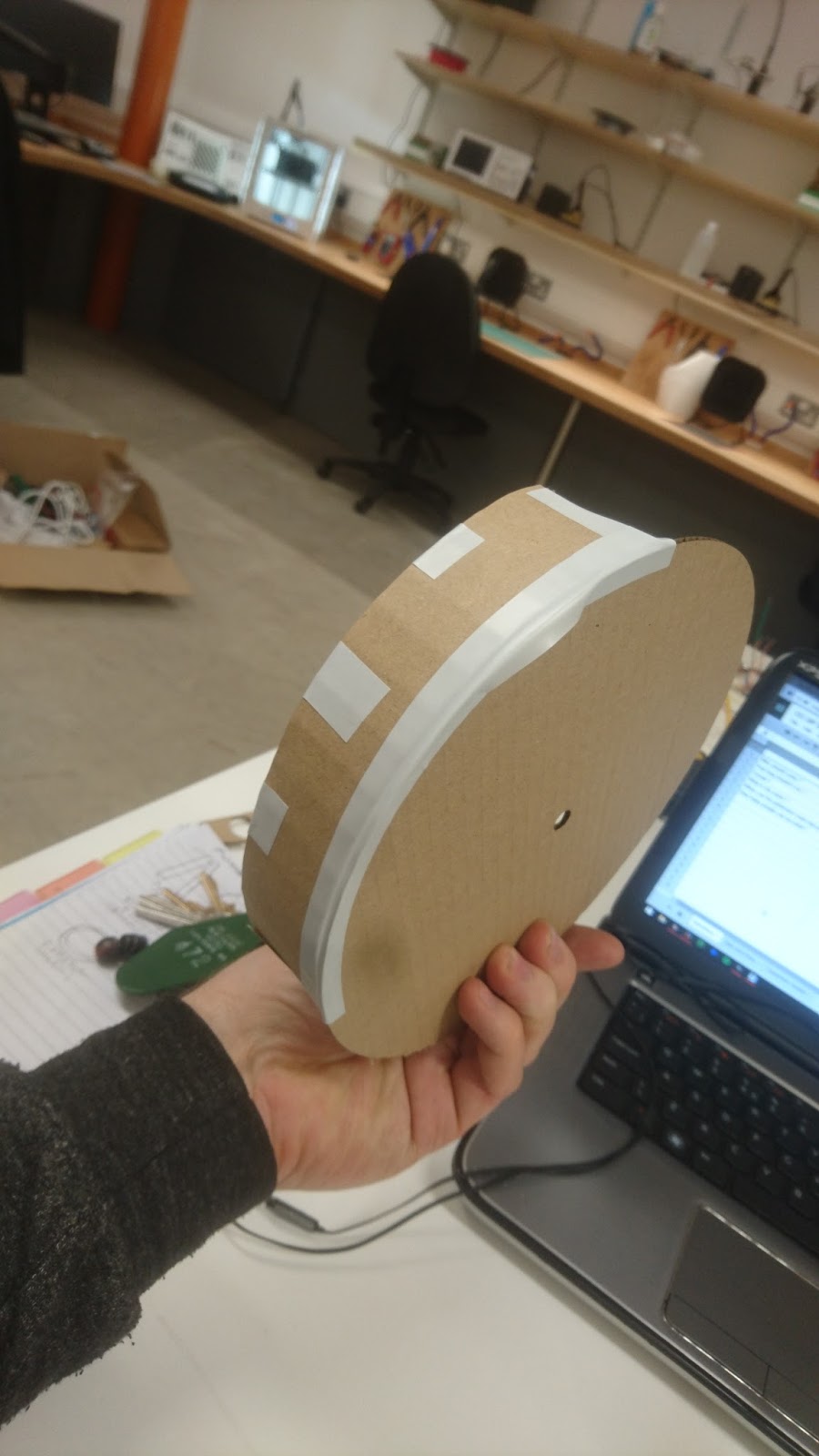
To get these models in the real world I took advantage of the university's Epilog M2 40 Laser Cutter. I was able to cut everything out of cardboard and construct a model.


The redesign

During my motor tests I hit a brick wall. The weight of the body section was a far greater than I had first calculated and made it quite impossible for it to lower and raise.

After some consideration I knew that I had to change course before it was too late. I wanted to keep the concept of surveillance within the core design of the character but also reduce the articulation. This reduction of an axis of movement was a difficult challenge to face but below represents a collection of the sketches made in this new design process.

I decided to make the focus on the "head" of the robot, or in this case the "eye". This eye rotates 360 degrees clockwise and anticlockwise. The eye is an assembly of lenses attached to a disk held up with an axle.

The new design addresses the mechanical difficulties of the previous design while retaining much of the core character.

The next step is to build a working prototype which is scaled down. With this I will be able to build a working system that can by built at different scales. I can then find the limits of the system in terms of scale.

Below is a collection of sketches made during the design process.